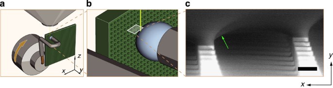
We observe a higher microscale receding angle for the capillary bridges on the nanograss-covered micropillars as compared with the smooth micropillars. We propose that this is due to a self-similar depinning mechanism, for which the total pinned length of the contact lines at each level of the hierarchical roughness must be taken into account.
Considering a droplet sitting on a surface comprising multiple levels of roughness features (Fig. 5a), the apparent macroscopic contact line of the drop comprises the zeroth level of hierarchy and will actually be divided into many smaller contact lines, each sitting on top of a roughness feature at the first level (Fig. 5b). The receding angle exhibited by the capillary bridges local to the first level of hierarchy will be different from that exhibited by a drop observed at the zeroth level  (the macroscopic contact angles measured by a goniometer). The microscale contact angle
 on smooth micropillars observed by the ESEM is synonymous with
 . If the contact lines of these first-level capillary bridges are observed at an even smaller length scale, we hypothesize that they will be divided into even smaller contact lines, each sitting on top of a roughness feature at the second level of hierarchy (Fig. 5c). The receding angle of these second-level capillary bridges local to the second level of hierarchy
 will in turn be different from that observed at the first length scale. This self-similar pattern of subdivided contact lines and differing local contact angles may be continued down successive levels until reaching a level n that exhibits a homogeneous wetting interface25. At this cutoff level, the contact line on each roughness feature will be continuous. Thus, the actual pinned length of the apparent contact line at any level will be determined by the geometry of the roughness features at all smaller levels, if they exist. If the tops of the roughness features at the cutoff level are also flat, as is the case with the smooth micropillars, the local receding angle should approach the intrinsic receding angle, that is,
 .
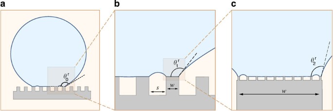
(a) A liquid droplet that rests in a Cassie–Baxter state on a hierarchical surface exhibits an apparent receding angle θ0r. (b) The apparent contact line of the drop is divided into many smaller first-level contact lines, each at the top of a first-level roughness feature with width w and spacing s. Each of these first-level contact lines sits at the base of a first-level capillary bridge, which has a local receding contact angle θ1r. (c) The apparent contact line of each second-level capillary bridge is further divided into smaller second-level contact lines, each atop a second-level roughness feature. Each second-level contact line sits at the base of a second-level capillary bridge, which has a local receding contact angle θ2r.
The apparent contact line at any level can be projected onto the tops of the roughness features of the next smaller-scale level. The projected contact line will traverse a number of individual roughness elements, as illustrated in Fig. 6a, in which a portion of a projected contact line traverses seven square micropillars. This hypothetical drop will be pinned to both the peripheral micropillars and the interior micropillars, but significant distortion occurs only at the micropillars that sit directly under the projected contact line. The total pinned length is simply the perimeter of each micropillar P multiplied by the number of peripheral micropillars N. The effective pinned fraction φ of a projected contact line of length l can then be found as φ=NP/l. As the number of micropillars per length N/l is equal to the inverse of the average micropillar pitch τ, the pinned fraction can be rewritten as φ=P/τ. Thus, if the roughness features are sparsely spaced, only a small fraction of the projected contact line will be pinned (Fig. 6b, row 1). However, if the pillars are packed densely, then the pinned fraction will increase. In some cases, φ may be greater than 1, indicating that the sum of the lengths of the contact lines of the peripheral capillary bridges is greater than the length of the projected contact line (Fig. 6b, row 2).
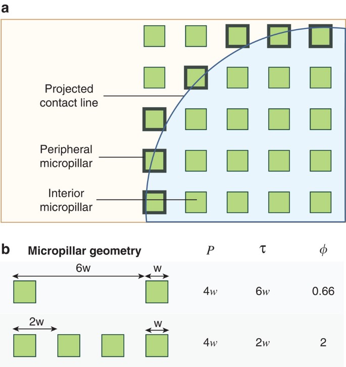
(a) A contact line projected on a textured surface will be pinned to a number of peripheral micropillars. (b) Effect of texture geometry on pinned fraction. Micropillars with sufficiently dense spacings will result in pinned fractions greater than 1.
The pinned fraction concept can be further applied to structures with multiple hierarchies. Just as the apparent macroscopic contact line of a millimetric drop can be projected onto the tops of the micropillars to obtain the number of peripheral micro-capillary bridges, the contact lines of the micro-capillary bridges can be projected onto the tops of the nanoscale features to find the number of peripheral nano-capillary bridges. The total pinned fraction of a macroscopic contact line at the zeroth level Φ0 can be calculated for a surface with n hierarchical roughness levels by the product of the pinned fraction at each level:

where Pi and τi are the perimeter and average pitch, respectively, of the roughness features at the ith level of the hierarchy. The quantity l0Φ0 then gives the total pinned length of a projected contact line of length l0 sitting on a surface with n roughness levels. This total pinned length is equal to the sum of the lengths of contact lines of all peripheral capillary bridges at the nth hierarchical level. Similarly, if we wish to find the total pinned length for a subset of levels starting at j<n, we calculate Φj by evaluating equation (1) from i=j+1 through n:

The total pinned length is then given by ljΦj, where lj is the perimeter of a roughness feature at the jth level. This is useful, for example, in calculating the total pinned length of an individual micro-capillary bridge sitting on a micropillar that itself has additional finer roughness levels. In this case, lj is equal to the perimeter of the micropillar, and  is equal to the product of the pinned fractions on the second level and all finer levels. Finally, as the contact line at the nth level is continuous, it is not subdivided any further and the pinned fraction Φn=1.
Surprisingly, equation (1) indicates that adding multiple roughness levels does not necessarily decrease the total pinned fraction. As an example, consider a surface with one roughness scale consisting of sparse micropillars, such that Φ0=φ1<1. If we impart an additional level consisting of sparse nanograss such that φ2<1, then the total pinned fraction becomes Φ0=φ1φ2, which is less than the original pinned fraction. Indeed, for many familiar hierarchical superhydrophobic surfaces such as lotus leaves, there are two roughness scales, and the pinned fraction at both levels is less than one52. However, if the nanograss features had been very densely packed such that φ2>1, then the total pinned fraction of the dual-level surface would have been greater than that of the single-level micropillar surface: φ1φ2>φ1. This is the case for some nanotube surfaces for which the pinned fraction can be greater than 3, leading to very high droplet adhesion53.
The adhesion force of a drop to a hierarchical superhydrophobic surface with discrete roughness features can be determined by considering the force due to surface tension acting along the bases of the capillary bridges. By considering a vertical force balance on the drop (Supplementary Note 2 and Supplementary Fig. S1), the adhesion of the entire drop is predominantly dictated by the vertical component of surface tension acting at the peripheral capillary bridges. The force pinning a single capillary bridge at the jth level can be written as 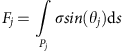 , where Pj is the perimeter of an individual roughness feature onto which the bridge is pinned, σ is the liquid–vapour surface tension, θj is the contact angle local to jth level, and ds is a differential length along the perimeter. In the present case, to estimate the maximum adhesion force before detachment, we approximate the contact angle as being uniform around the entire perimeter of the micropillar and equal to the receding angle local to the jth level
 , so the previous expression simplifies to
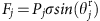 (see Supplementary Note 3 for discussion of error analysis). If there exist additional roughness levels, the adhesion of the jth-level capillary bridges will be determined by depinning of capillary bridges at the smaller levels. This will in turn affect the value of
 .
Because of the mechanism of self-similar depinning, the adhesion of the entire jth-level bridge will be governed by the detachment of the capillary bridges atop features at the nth level. As the local receding contact angle at this final level,  will be approximately equal to the intrinsic receding angle θr, the vertical force exerted by a single nth-level peripheral capillary bridge due to surface tension will be
 , where Pn is the perimeter of a roughness feature at the nth level, and θr is the intrinsic receding contact angle. Finally, the vertical adhesion force of the entire drop can be found by summing the forces due to all of the peripheral nth-level capillary bridges:

where l0 is the length of the projected macroscopic contact line. By normalizing the vertical adhesion force predicted by equation (3) to the adhesion force of a drop with an equivalent base radius on a smooth surface, given by (F/l)s=σsin(θr), the resulting ratio  suggests that Φ0 can be considered as a multiplier that reflects the strength of the pinning on the textured surface as compared with that on a smooth surface. Therefore, when Φ0>1, the adhesion force per unit length of a contact line on a textured surface should be greater than that on a smooth surface, and vice versa. Because of self-similarity, the adhesion force per unit length of a single capillary bridge atop a feature at the jth level is the same as that of a macroscopic drop sitting on a surface consisting of a texture with levels j+1 through n:

In other words, the adhesion force per unit length of the microscopic contact line of a micro-capillary bridge on a single nanograssed micropillar is the same as that of a macroscopic drop on a surface with just a nanograss texture.
To validate our hypothesis of self-similar depinning, we compared the adhesion force predicted by equation (3) with experimental observations. Using a tensiometer, we measured the force required to pluck a millimetric drop vertically off of two types of surfaces: smooth micropillars and nanograss-covered micropillars (Fig. 7a). There is a significant decrease in adhesion to the nanograss-covered micropillars as compared with the smooth micropillars. Additionally, as the spacing ratio s/w increases, the density of micropillars and the adhesion force both decrease. For both the smooth and nanograss-covered micropillars, the pinned line fraction at the first level is given by φ1=4w/(w+s). In the case of the nanograss-covered micropillars, there is a second roughness level (n=2) at a nanometre scale with a pinned fraction φ2=0.18±0.05 measured from SEM images (Supplementary Fig. S3).
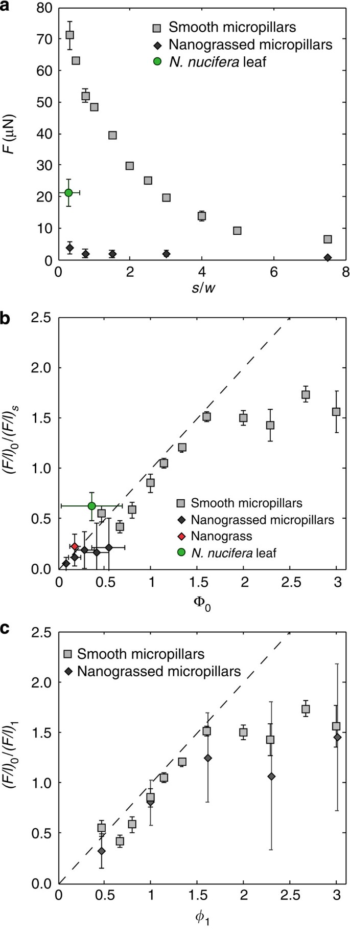
(a) Adhesion force versus spacing ratio for smooth micropillars, nanograssed micropillars and a N. nucifera leaf. (b) Ratio of measured adhesion force per unit length of the contact line of a macroscopic drop to that on a smooth surface versus total pinned fraction for smooth micropillars, nanograss micropillars, flat nanograss and a N. nucifera leaf. Deviation at large pinned fractions is due to interaction of capillary bridges. Dotted line indicates the ratio as predicted by equation (3). Error bars indicate s.e. (c) Adhesion force per unit length of projected contact line of a macroscopic drop normalized to remove the effect of the nanograss hierarchy, plotted against the pinned fraction at the first hierarchy. For the case of nanograssed micropillars, (F/l)0 was obtained by measuring the adhesion force of a drop on a nanograss surface and normalizing with the projected length of the contact line. For the case of smooth micropillars, (F/l)0 is simply  . Dotted line indicates the normalized force as predicted by equation (4). Error bars indicate s.e.
Figure 7b shows (F/l)0/(F/l)s— the measured adhesion force per unit projected length of the contact line of a macroscopic droplet normalized to that on a smooth surface—versus the total pinned fraction Φ0. For both single- and dual-hierarchy surfaces, and even the lotus leaf, the data collapse onto the line predicted by equation (3). There is a deviation at denser pillar spacings because the roughness features are no longer in the regime of sparse defects, and the peripheral capillary bridges begin to interact with one another. This leads to a larger local receding angle between adjacent pillars as shown in Fig. 3b, thus we would expect the vertical component of surface tension to decrease. Indeed, we find that the normalized adhesion at larger pinned fractions (Φ0≥1.5), which corresponds to the regime of dense spacings, is lower than that predicted by equation (3).
The effect of the second level of hierarchy can be factored out by normalizing the measured vertical adhesion force per unit projected length of the contact line of a macroscopic drop from equation (3)  with the force per unit length of a capillary bridge on top of the micropillars from equation (4) evaluated at j=1
 to obtain the ratio (F/l)0/(F/l)1. Hence, plotting (F/l)0/(F/l)1 against φ1 should yield similar results for both smooth micropillars and nanograssed micropillars, as the effect of the texture on top of the micropillars is cancelled. Indeed, Fig. 7c shows that the normalized adhesion forces measured on nanograssed micropillars match well with those measured on smooth micropillars, and as predicted, both lie along a line with a slope of 1. Furthermore, the normalized adhesion forces on the nanograssed micropillars display a similar plateau due to capillary bridges interacting at the microscale level, as seen with the smooth micropillars. However, as the receding angle local to the micropillars is greater for the nanograssed micropillars, they will begin interact at wider spacings than for smooth micropillars and exhibit normalized adhesion forces that are lower than predicted. One might expect that adding any additional level of microtexture to the nanograss would have decreased the adhesion force per unit length. Interestingly, we find that the normalized adhesion of nanograssed micropillars with small s is greater than that of a surface with just a nanograss texture. This can be explained by realizing that the total pinned fraction involves the product of the pinned fractions at both levels, and since φ1>1 for s<30 μm, we see how dense nanograssed micropillars (φ1≥1.5) can exhibit greater normalized adhesion per unit length than a surface with just a nanograss texture. This result is counterintuitive, and shows how additional roughness levels will decrease the adhesion force per length only if the pinned fraction at that level is less than one. As the pinned fraction of a particular level is increased beyond one, that level will act to increase the adhesion force per unit length. However, the adhesion force will saturate when the pinned fraction at that level reaches a critical value (φi≥1.5 in the current case) above which the capillary bridges at that level begin to interact.
Using a novel technique for observing the dynamic behaviour of a three-phase contact line and quantitatively measuring contact angles at micron length scales, we show direct evidence that the Gibbs criterion is satisfied at these length scales. We introduce a model that describes a self-similar depinning mechanism and accounts for the effects of the hierarchical roughness features. The model described in equation (4) shows that the adhesion force per unit length of the projected contact line may be either increased or decreased by adding multiple length scales of roughness depending on the pinned fraction of each level of hierarchy. This finding is important for designing surfaces with minimal adhesion, as it quantifies the effect of multiple length scales on the adhesion of a liquid drop on a textured surface: to reduce adhesion, the product of the pinned fractions at all length scales must be less than one. Furthermore, two micropillar geometries that have identical area fractions may have different pinned fractions depending on their perimeter and spacing, whereas any attempt to calculate pinning or hysteresis based on area fraction would yield identical results for the two surfaces. In agreement with our mechanism, experiments have shown that the hysteresis differs depending on the micropillar perimeter and tip geometry24,40,53. Our technique could also enable the detailed imaging of contact line behaviour on complex pillar geometries and on intricate biological surfaces, such as water strider legs54 and fibre arrays55.